
Application of Softwares and Tools in Nuclear Grade Fan Design
In terms of fan selection, advanced aerodynamic performance selection software is used to make the reliability, safety, progressiveness and economy of the provided products meet the standards and requirements of nuclear power engineering.
Blade design is the key to fan design. In order to improve fan performance, we have conducted extensive experiments and thorough analysis on the vortices generated by the internal flow of the fan casing. Due to the work of the impeller, vortices are inevitably generated in the airflow inside the casing. Without optimizing the blade design, various losses will increase, especially secondary flow losses, including separation losses, vortex losses, etc.
The enhancement of these losses will disrupt the airflow flow state, reduce fan efficiency, decrease pressure rise, and increase noise. Especially at the tip and root of the impeller, the tip of the impeller generates clearance flow and scraping vortices during blade rotation due to clearance and the boundary layer of the ring wall; Due to the presence of the hub boundary layer at the root, there is a pressure gradient in the channel between the blade bowl and the blade back, resulting in channel vortices. The development and enhancement of these harmful vortices will seriously affect the performance of the fan.
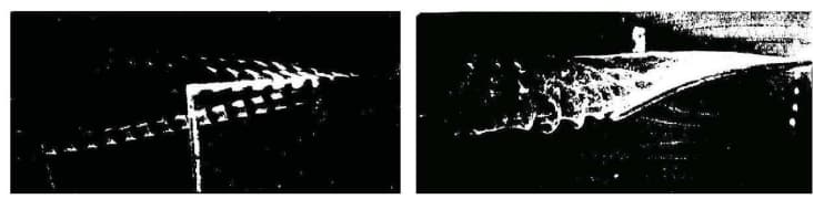
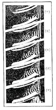
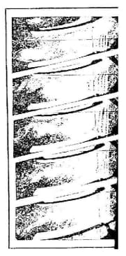
SHUANGYANG FAN's Engineering Technology Center, in collaboration with Shanghai Jiao Tong University, utilizes the university's aircraft engine theory research technology and computational fluid dynamics laboratory for research and development, and conducts extensive experiments through a national level aerodynamic laboratory. To improve the efficiency of the fan, a study on the mechanism of flow field display was conducted before design. The analysis of the development and distribution of gap vortices flowing from the root to the tip of the experimental blade shows that the larger the blade curvature angle, the greater the vortex intensity and the wider the range of vortices. In the blade channel, if the inlet angle of attack is high, it will cause separation vortices on the blade back, and it is a periodic separation vortex of unsteady flow. Due to the presence of the hub boundary layer at the root of the blade, there is a pressure difference in the blade channel from the blade basin to the blade back, resulting in channel vortices near the root of the blade. The secondary flow loss accounts for more than half of the total flow loss of the fan. SHUANGYANG FAN aims to minimize the secondary flow loss as much as possible by designing high-efficiency and low-noise fans.
Side view of tip vortex flow Top view of tip vortex flow
2D blade channel separation vortex flow Vortex flow in the blade channel
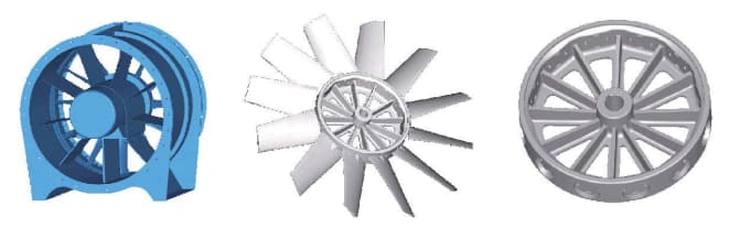
In terms of fan structure design, the most advanced international software I-DEAS is used to analyze and calculate the structural strength of the main key components of the fan, such as the impeller, casing, and transmission device, to ensure the reliability and reasonable matching of each part of the fan structure, minimize vortex impact and flow resistance loss in the flow channel, and reduce airflow and structural noise as much as possible to ensure the strength and reliability of the fan.
3D modeling of axial flow fan
Finite element analysis of impeller strength
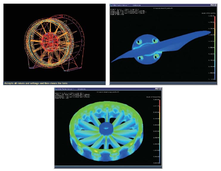
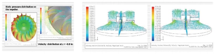
CFD flow field verification
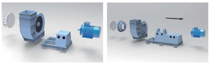
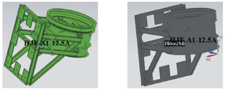
3-D modeling of centrifugal fan
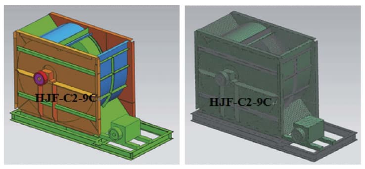
Centrifugal fan model diagram Finite element model diagram of centrifugal fan
Axial fan model diagram Finite element model diagram of axial fan
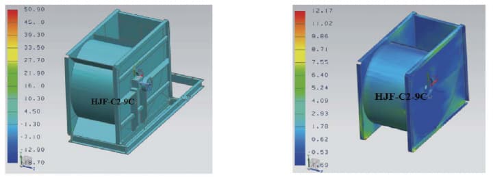
Stress analysis diagram of centrifugal fan
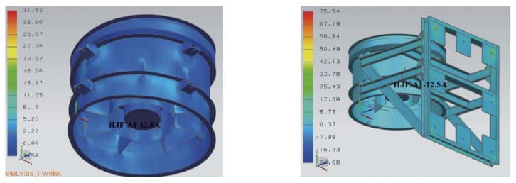
Stress analysis diagram of axial fan
SHUANGYANG FAN is equipped with domestically leading design software and uses specialized damper design software for damper performance and structure.
The design of the damper adopts both two-dimensional and three-dimensional drawing software. Two dimensional drawing software can effectively convert design content into drawing information, facilitating the understanding and comprehension of product systems by other technicians and processing personnel. In conjunction with three-dimensional drawing software, it can be used for model making, simulated assembly, and simulated operation testing of products. Its advantages include:
1. Intuitive display of the solid shape of each component of the damper;
2. Conduct comprehensive analysis of motion speed and trajectory to identify potential issues during the product design phase;
3. Conducting virtual assembly, simulating test plans, and shortening the testing time and product development cycle have played a significant role in the development of new products and the improvement of traditional products, making verification simpler and faster. Has good interactivity with other drawing software and can communicate effectively with various design institutes and collaborating units.
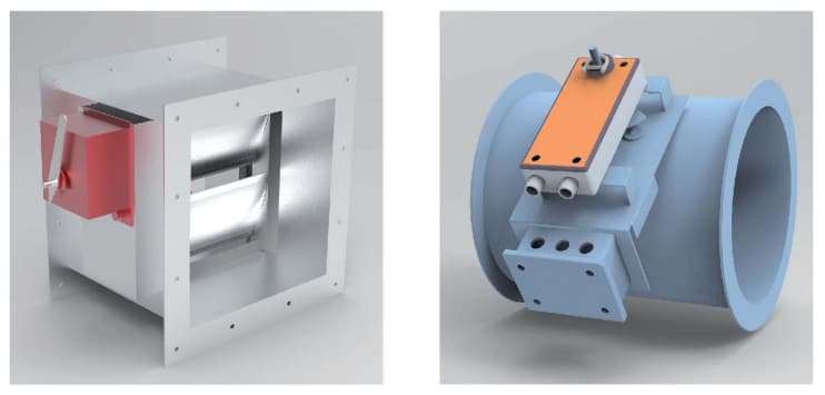
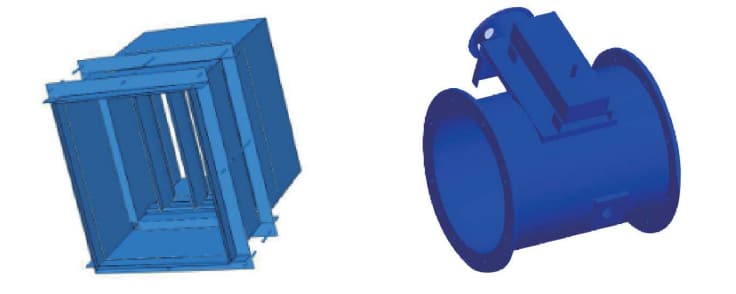
Schematic diagram of nuclear grade fire damper
In terms of the structural design of the fire damper, the most advanced international software ABAQUS is used to conduct stress analysis and calculation on the main key components of the fire damper, such as the frame, blades, and shaft supports, to ensure the reliability and reasonable matching of each part of the fire damper structure, minimize flow resistance losses in the flow channel, and ensure the strength and reliability of the fire damper.
Model diagram of nuclear grade fire damper
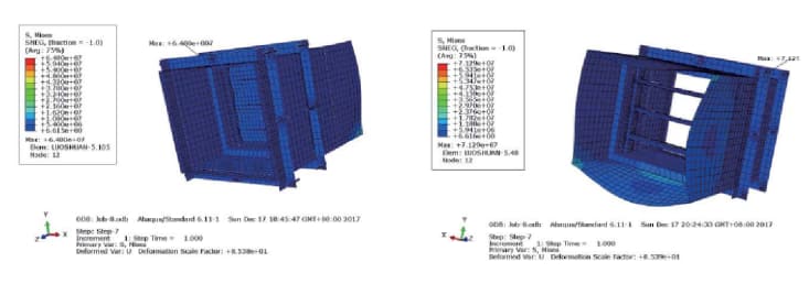
Stress cloud map of damper (blades closed) Stress cloud map of damper (blades open)
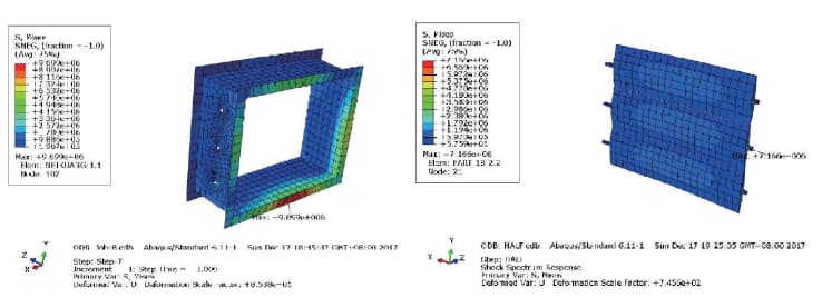
Stress cloud map of frame (blades closed) Stress cloud map of blade (blades closed)
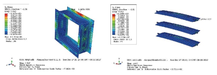
Stress cloud map of frame (blades open) Stress cloud map of blade (blades open)
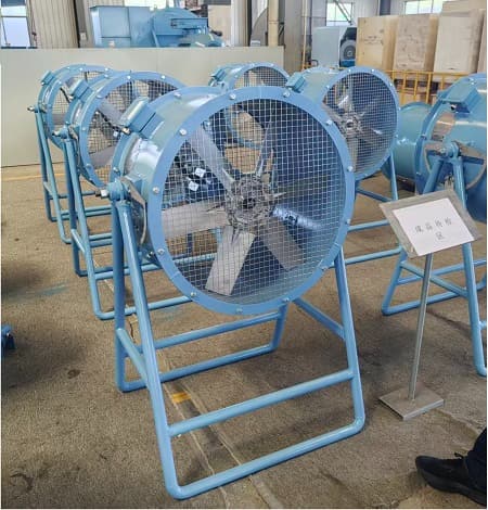 Mancooler (Workstation) Fans — Why Your Factory Needs the Right One
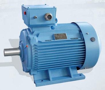 Motor Classifications in Industrial Fans
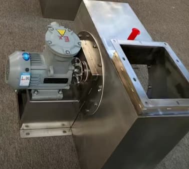 Materials for Explosion-Proof Fan
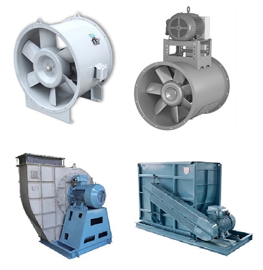 Direct Drive vs. Belt Drive in Axial Fan and Centrifugal Fan